Getting wrapped up in a thick wool blanket
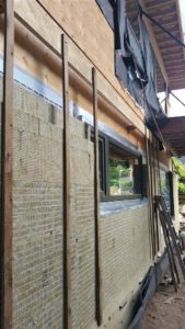
I am pleased to advise that the installation of the exterior water/air barrier, and 6″ of exterior ROCKWOOL mineral wool insulation panels is going well. Over the last 2 weeks I have completed the first storey of the south and west elevations. The encouraging part is that the west elevation looks like it will only take 3 days total compared to the week plus the south elevation took.
Now on the south, I had a lot of figuring out to do. We had not yet chosen exterior lights for beside the exit doors. The choice would effect where the electrical box would be located as I want the top of the lights to line up with the top of the doors. I also had to secure and seal the final french door (for the office) before I could detail that opening. I then designed and sourced some walkway lighting that will be mounted approximately knee height on the wall and shine down and cast a warm glow along the walkways flanking the house. Finally, the south elevation contains one of the two basement foundation wall science labs and I needed to figure out a way to terminate the sensor wires and also install the water injection system that will be used to wet up the ICF and mineral wool insulation under controlled events.
By the time I got to the west wall, I had figured out all the steps and also easiest way to install the ROCKWOOL panels using the table saw to accurately cut the required sizes and angles. I also discovered that the primer for the foil faced membrane made an EXCELLENT adhesive to stick the various cut insulation panels together, removing the need to use auxiliary screws with plastic washers to hold panels in place temporarily until the furring strips could be installed.
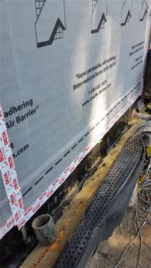
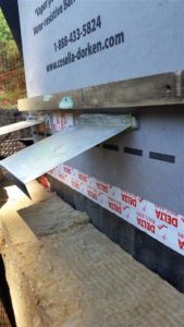
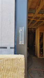
Now, I did not want these clips attached to the foundation were they would have to penetrate the waterproofing membrane. So I designed this system that clips to the sheathing above grade. I sandwiched an aerogell gasket (R4 for only 10mm) between the S.S. clip and the sheathing to reduce thermal bridging. It is important to ensure the aerogel is encased in a wrap of some sort to retain all the microscopic ‘powder’ that make up its high R value.
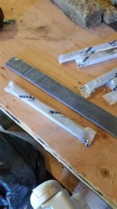
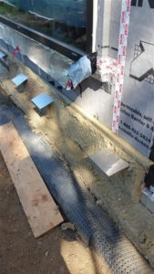
With the base of wall detailed I could then start to install the wall insulation. In our design, this is two layers of 3″ ROCKWOOL ComfortBoard 80 with staggered seams.
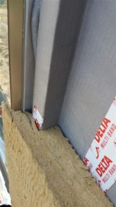
One of the most difficult parts of this installation was going to be how to ensure the battens were all installed at the same correct elevation (otherwise it would make installing flashing level and ensuring a nice site line difficult). This was solved by installing a rigid long board – header – I used left over blocking I-joist and some dimensional lumber, at the top side of the 1st length of battens. I set the board off of the sheathing by the depth of the exterior insulation with blocks I cut out of left over lintel and post pieces. Now I just had to line up the battens with the top of the header and with the studs (later are easily visible due to sheathing nailing pattern visible above the membrane), and screw to the header to ‘hang’ them in place. Installing a second screw in through the batten into the header ensures the batten stayed plumb. This allowed me to install the full batten system and the bottom bug screen without screwing any of it into the wall. For me this was a necessary step so that I can still slip in and attached my base of batten flashing a little later (a sequencing issue because I will have the flashing corners bent up by a pro with a brake to ensure a nice finished look). Even if I did not have the base of wall flashing issue, this method of hanging the battens made their installation MUCH faster and easier. On the west wall, I installed the mounting board and all of the full length battens for the wall (including pre-drilling holes at 16″, counter sinking, and treating with wood preservative) in under an hour.
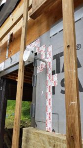
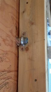
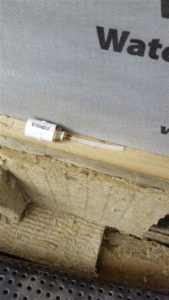
Update July 30, 2018 – My electrical inspector did advise he was going to need to see a strain relief connector added to the inboard side of this nipple.
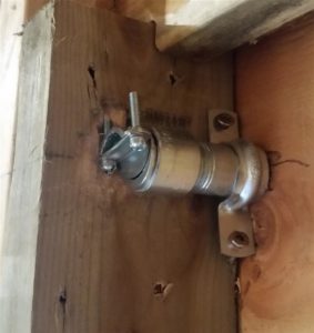
End of update
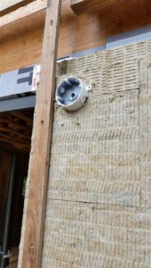
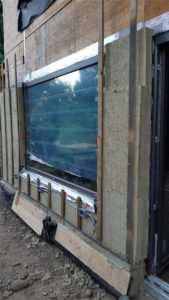
I mounted the electrical boxes for the exterior pathway lighting to pressure treated 3/8″ plywood strips. I then screwed through the battens into the plywood strips with spacers between the plywood and battens to maintain the required setback so the box sat flush with the exterior plane of the to be installed siding. To minimize penetrations, I looped the conduit down under doorways on the exterior side of the wall to carry on the circuit on the other side of the entrance. You can also see the furring strips and perforated stainless steel bug screen installed in the above photo. Later a base of rain-screen flashing will be slipped behind the furring strips and screwed through the insulation to the previously installed horizontally 2×2 blocking. This prevents fasteners from penetrating the sheathing membrane and also prevents the thermal bridging that would be present in a cross cavity metal flashing.
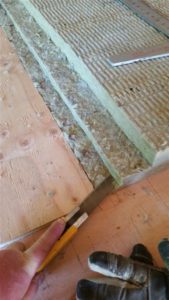
Confession! – As I was preparing this journal entry, I realized I have forgotten to install the foil faced membrane that is to provide cross cavity evacuation of any water that gets behind the cladding and insulation. This was to install about the same height as the lighting circuit. I will need to figure out a way of cutting out the insulation to install it now on these two completed walls. 🙁
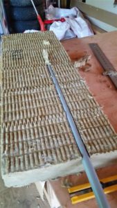
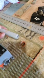
Somewhere along the way I came across the below method for installing a pull chord in your conduit.
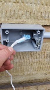
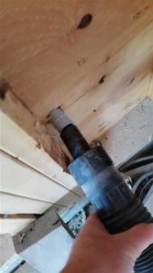
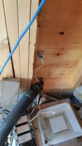
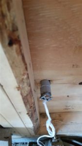
Part of the recent effort also involved terminating the building science lab installed into the foundation.
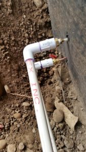
I brought the piping for the injection ports and the sensor wiring to the area of a to be installed PVC electrical box (12×12) that will be mounted flush with the surface of the sidewalk and sealed with a gasketed stainless steel lid.
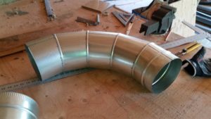
Also as promised, here is also a photo of 2.0 diameter 7″ 90º duct elbow. As you can see, this takes up quite a bit of real-estate. I still have to go through my routing of the ducts and ensure there is enough room for this elbow at all locations before placing the order for these special order (and expensive) fittings.
I will continue working on the exterior insulation for several weeks more and then start on the siding. There is also some exciting news about progressing on another major milestone, but I will delay reporting on it till later for fear of jinxing it.
Thanks for visiting!
“We have enough people who tell it like it is—now we could use a few who tell it like it can be. ” —Robert Orben (born 1927) Magician, Comedy Writer
“The road of life twists and turns and no two directions are ever the same. Yet our lessons come from the journey, not the destination.” —Don Williams Jr. (born 1968) Novelist, Poet
“To thrive in life you need three bones. A wishbone. A backbone. And a funny bone.”
—Reba McEntire (born 1955) American Country Music Artist

Hi again. Fellow owner-builder out in white rock building very slowly (almost 3 years now for me and roughly same stage as you :))
I was curious about the use of the metal connector clamp attached to the pvc conduit. Is there any issue with this metal connector not being grounded as would be required if it were to attach directly to a metal box/conduit… reason I ask is I am ripping out my exterior light and recep boxes and replacing with surface mount weatherprood pvc ones with threaded center KO and looking at how to meet the requirement of clamping wire as it enters box.
There appears to be some plastic twist compression stress relief connectors but they are like 5$ each..
Hey Phillip – Thanks for stopping by again. Totally understand on build time. I am now at 3 years and almost 3 months since I first started taking the old house down.
I do not believe this to be a problem because it represents such a small amount of metal. I would check with your electrical inspector to be sure (they are there to help you and usually happy to do so). When you talk to them, discuss ‘bonding’ not grounding as this is the proper term for what you are referring to. The only ‘grounding’ is the bare copper conductor between the main panel and the grounding rod/plate. All the rest is referred to as bonding.
But you have brought up a good point, I may need to add the clamps to the ends of the nipples projecting into the stud cavity from the back side of my lights. I will need to ask my inspector the next time I see them. Realistically, the sealant I will force into the interior of the nipple to seal around the wire and the fact that the ground will be secured in the light box, are more than enough to provide strain relief. After all, you do not have any strain relief on individual conductors run in a conduit. I will try to remember to post back their reply here.
Hey Phillip – very late reply, but yes I needed to put a strain relief on the end of the nipples. Not an easy task considering the limited depth of the 2×4 stud space. I used a 1/2″ Rigid conduit coupling that is threaded all the way and cut it in half. I parred it up with a standard strain relief coupling that I also ground down to shorten the threaded portion.
I’ve enjoyed your blog, which I found from your youtube videos. I have a few questions on this post.
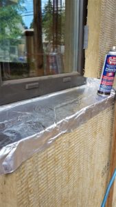
1) What type of foil-faced flashing did you use as your secondary sill membrane? What brand, name, etc?
2) Did you apply the secondary sill membrane to the window frame or did you apply to to the rough opening under the window frame so the window sits on top of it. It seems like attaching to the primary sill membrane on the rough opening would be a little redundant as I don’t see how water could get under the secondary sill membrane. (Though I would not risk it and leave bare exposed wood in the rough opening, so something would have to flash it.)
3) How well does the foil-face flashing adhere to the mineral wool? Did you need the Tac spray adhesive or did the butyl adhesive of the membrane work sufficiently.
4) You mention the Tac spray adhesive worked well gluing mineral wool pieces together. Do you think it would be sufficiently strong that you could temporarily tack the mineral wool to the buliding’s OSB or plywood until you add the battens for permanently securing the mineral wool? What about a second mineral wool board onto another mineral wool board?
Thanks. I’m designing a house with 9″ mineral wool exterior insulation using 3 layers of roxul board. And have had a little issue thinking of a way to add a secondary sill membrane to direct most water to the outside of the mineral wool. Also, temporary gluing the roxul up on the wall would help eliminate unnecessary screws going in, risking a miss of the stud and puncturing in my air barrier.
Hi Joe, Thanks so much for visiting both my website AND YouTube Chanel. Really appreciate the follow up questions.
1) Any foil faced membrane should work but in this instance I used Soprasolin HD from Soprema (http://www.soprema.ca/product/soprasolin-hd-549/). It is very nice to work with and seals fairly wall in warmer weather. In colder weather you probably want to use some form of primer/activator or a heat gun (this would be true for any brand). I have also used ProtectorWrap PS45 in the past and it too is really nice to work with and seals well.
2)For an exact record of steps for sill membrane see the rough opening preparation guide I put together. https://www.theenclosure.ca/cms/wp-content/uploads/2017/01/WindowFlashingBestPractice.pdf I too agree that the two layers seemed redundant but the secondary does not extend as far up the jambs and also do not form an air barrier. If doing again, I would discuss with my envelope gurus at RDH and look at ways to minimize the primary membrane (say by extending the permeable membrane up around and onto the top surface of the buck. But for this time, I just followed the instructions provided by the very intelligent and experienced people at RDH.
3/4) You definitely need to use the Protecto-Tac spray to adhere the membrane to the mineral wool. You want to securely affix the membrane to the mineral wool so that it says nice and smooth for the best drainage characteristics.
You mention sticking to OSB or plywood. You would NEVER be doing this. You MUST have a WRB installed between the insulation and sheathing (it is required by code and would be a very bad idea to ignore even if was not in code). And I am firmly in the camp that your WRB should also be your air barrier. And detailing with a self adhered membrane like Delta Vent SA just makes this task SO much easier. The roughness of the product also add a significant resistance to the Roxul sliding down the wall under the weight of cladding adding a further safety factor.
This spray has been awesome for sticking the ROXUL slabs to my WRB for prolonged periods (weeks in some cases) until able to mount the furring strips. It also works really well to stick two or more panel layers together. Especially if you spray both layers. So I typically spray the vertical on bottom edges of both panels and then just the back side around the perimeter of the panel I am just adding before lifting in place. You defiantly do not want to spray the whole surface or you will go broke. I am paying just under $20 per can when I buy per dozen and a can does not go very far (maybe 10-12 panels)
With that said, you will almost surely need to come up with another method of attaching and securing if going to 9″ of MW. 6″ is pretty close to the limit of just using battens and screws from a structural point of view. If going thicker you are probably going to be forced by engineering to use some form of squash blocks or clips to mount the furring strips to, in order for the furring strips to have enough resistance to settlement under the weight of your cladding. Something like the Cascadia clips would work http://www.cascadiawindows.com/products/cascadia-clip, but they only go to 8″. And even at 6″, you can only use the furring strip/screw method for light and medium weight cladding.
My biggest piece of advise to ensure you hit the studs is to do the assembly as a rolling progress. I will be explaining this a lot more in my next post (hopefully will write this weekend), but I am using temporarily mounted headers to attach my furring strips to in order to ensure they are perfectly plumb, and I am doing this step when the top of the furring strip is over bare plywood so that I can still see the stud nailing patterns. SO I add a course membrane (5′) to the wall, do all my base of wall insulation and flashing details, and add the ROXUL panels to within 6″ below the top of my membrane. I then mount the 8″ furring strips to a header I have temporarily mounted above using a digital level at the 8′ elevation (above the height of the first course of membrane). I line up the furring strips with the top of the header directly over a stud nailing line. I attach the strip to the header with two screws ensuring a perfectly plumb alignment. This allows me to ensure as I screw through the insulation, that as long as I am perfectly perpendicular to the insulation, I will hit the stud, and it also ensure that the base of the furring strips (and therefore my siding) is going to be perfectly level.
If you are in the Lower Mainland area, please contact me privately and we can arrange a site visit to give you first hand info/experience on the various concerns you have. I will be working on the envelope till well into November.
Hope this helps. Cheers
Thanks for your thorough reply. Your link to your Window Flashing Best Practices helped a lot. I don’t think that article was available as a journal entry, but I may have missed it somehow.
Great to hear that the glue holds the roxul to your WRB and other roxul boards. That’s what I was wondering. And of course I would be using a WRB, I chose my words poorly. I like the Delta Vent SA, several liquid applied WRBs, and Zip sheathing. Some sort of vapor open, air and weather barrier.
Thanks for your concern about screwing through 9″ of exterior insulation. I’ve thought about it, and have come across the Cascadia clips. However, when researching furring strips and various sidings, I’m certain I’m safe. I’m only applying fiber cement siding to it (a low weight siding option). (Whether or not an inspector will pass off on it, is another question, as you found out in your most recent journal entry.) You’ll really find this presentation fascinating: http://www.phius.org/NAPHC2017/Aoki-Kramer-Attaching-Cladding-with-Long-Screws.pdf Their testing showed attaching furring strips with screws would be safe with even 12″ of exterior roxul!
Other links about furring strip attachment, that I’m sure you’ve come across, are here, which lead me to believe that it could be possible:
http://www.greenbuildingadvisor.com/blogs/dept/musings/fastening-furring-strips-foam-sheathed-wall
http://www.greenbuildingadvisor.com/blogs/dept/qa-spotlight/how-attach-thick-layer-exterior-insulation
Your article about aligning the furring strips is helpful. Clever idea. Since, I’m going to be building a fake soffit at the roof line, I could adapt your technique by marking the stud locations on it and dropping plumb bomb lines from it. Before your technique, I was going to create a screwing jig that would be a block of wood with a drilled hole in it, that would keep the screw in the right planes. So that the screw can only be drilled straight, and in the right angle.
Thanks for the site visit offer, but I don’t live near by. I live in Kansas and am just working on doing my research for a future house.
Hi Joe,
Thanks for follow up and links.
Coincidence, I am currently going through the PHIUS paper. The author, Graham Finch from RDH, is my main building science mentor and had recently provided the paper to me for review.
If going with 9″ and screw method, I would seriously look at just using 3/4″ ext sheathing. This way you do not need to hit studs.Even with my method of placing the furring strips and trying to ensure a perpendicular screw in, hitting the studs is not easy. 1.5″ is a very small target! Just a slight degree variance when you are out 6″ makes a huge difference by the time you get to the sheathing surface. It would be even worse starting 9″ out.
If you have two stories, your plumb bob may not work as it is difficult from a structural standpoint to get studs to line up from floor to floor (unless doing advanced framing but then the framing dictates your entire house layout including where window and doors go and room layouts – I felt this was very much not worth it as with CI on exterior, the thermal bridging issues goes mostly away.). So I have one pattern of furring strips for lower floor and another for upper floor.
Good luck on project and let me know how you make out.